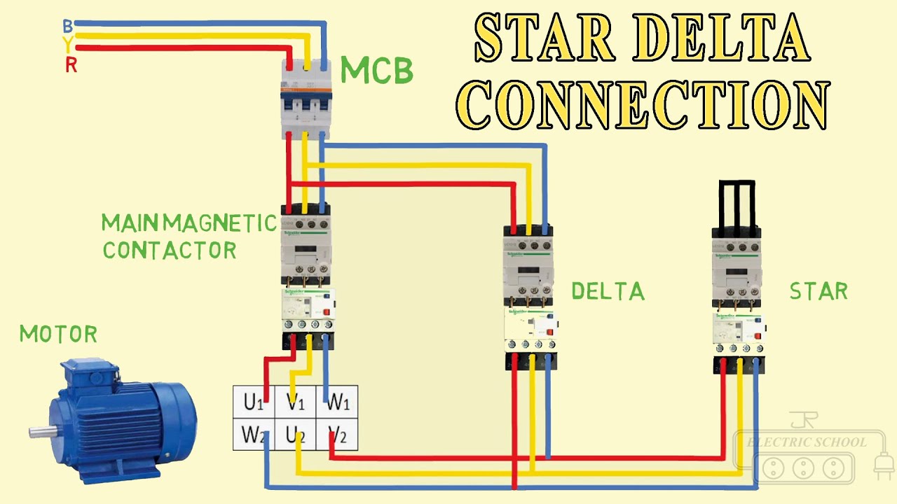
3 phase star delta motor connection diagram pdf
Descriptions: A Dual starter connects the motor terminals directly to the power supply. Hence, the motor is subjected to the full voltage of the power supply.
The Star Delta starter can only be used with a motor which is rated for connection in delta operation at the required line voltage, and has both ends each of the. At start, the line voltage is applied to one end of each of the three windings, with the other end bridged together, effectively connecting the windings in a star connection. In some cases, this may be enough to get the motor up to full speed, but most, as this is a constant voltage starter, the transition to full voltage will occur at part speed resulting in a virtual DOL type start. To step to full voltage, the star connection is opened, effectively open circuiting the motor, and the ends of the windings are then connected to the three phase supply in a fashion to create a delta connection. This type of starter is an open transition starter and so the switch to delta is accompanied by a very high torque and current transient. In most situations, there would be less damage to the equipment and less interference to the supply if a DOL starter was employed.
3 phase star delta motor connection diagram pdf
A Star-Delta starter is an electromechanical device used to start and control the speed of a three-phase induction motor. The Star-Delta starter includes a control circuit that typically consists of a timer, contactors, and overload relays. After the motor reaches a specific speed, the timer switches the winding connection to a Delta configuration to ensure the motor operates efficiently. This starter is widely used in industries where high-power motors are required, such as in oil and gas, mining, and manufacturing. However, it also has some disadvantages, including increased cost and complexity, longer starting time, and reduced torque during starting. This will include providing a schematic, power and control, PLC ladder, and wiring diagrams. We will also explain how the star-delta starter works and discuss its applications, as well as its advantages and disadvantages. On the left-hand side, there is the main contactor with a pneumatic timer. The main contactor is always energized. In the middle, there is the Delta contactor, which is equipped with a thermal overload for motor protection in the event that the motor exceeds the ampere rating set on the thermal overload.
After the motor reaches a specific speed, the timer switches the winding connection to a Delta configuration to ensure the motor operates efficiently.
.
Star Delta Starters. Remember electricity is dangerous and can be fatal, you should be qualified and competent to carry out any electrical work. Below are two examples of wiring diagrams for star delta starters from industry suppliers. By the end of this tutorial you will understand how these work. Always check with your manufacturer how, and if, a motor can be connected to a Star Delta starter. However, we will look briefly at other colour codes later in the article. Three phase motors are used in almost every commercial and industrial building. Inside a three phase induction motor we have 3 separated coils which are used to produce a rotating magnetic field.
3 phase star delta motor connection diagram pdf
Electric motors are essential components in various industrial applications and play a vital role in powering machines, pumps, compressors, and other equipment. However, when it comes to starting large motors, the initial inrush current can be significantly high, leading to voltage drops and potential damage to the motor windings. Related Posts. A star-delta starter is a widely used method for starting three-phase induction motors. It allows for a gradual reduction of the starting current, reducing the impact on the power supply and the motor itself. Typically, an automatic star-delta starter uses a time delay relay to switch between the star and delta connections of the motor windings.
Gram parsons musician
I think In the actual built circuit shown as picture posted, the star contactor is connected to the thermal overload terminal from motor side, which is more safety may be, not from delta contactor side as shown in power circuit diagram. AI-enhanced title. Linguistics and Language Linguistics and Language. Academic Documents. This is a starting. What is the use of timer in this circuit and how will delta operate after a delayed timing? Kindly consider whitelisting our website to allow ads. Search inside document. Did you find this document useful? It appears that you are using an ad blocker.
In a three-phase, motor the delta and star connection is the way in which the coils are connected. Star and delta connection is used to reduce the complexity of the wires that are required for a three-phase system connection. A three-phase motor will have three coils and it can be connected to the supply and the coil would have connections in both sides, in the below image we can see the R, Y, and B, it is the coils and they are connected to the supply and we can also see the three terminals that are interconnected or shorted in the image.
For Later. User Settings. Main supply will be connected to U1, V1, W1 and the configuration of star or delta will be based on the active contactor. The controlofthecontactorsisbythe timer K1T builtintothestarter. The main contactor is always energized. A Star-Delta starter is an electromechanical device used to start and control the speed of a three-phase induction motor. Close suggestions Search Search. What is Scribd? Joint this circuit with 3 phase supply to make full operation of main circuit and controlling circuit to AC Motor. The current in star is onethirdofthecurrentindelta,sothiscontactorcanbeAC3ratedatonethirdofthemotorrating. The Maincontactor. Culture Documents.


It not absolutely approaches me.
Absolutely with you it agree. In it something is also idea good, agree with you.