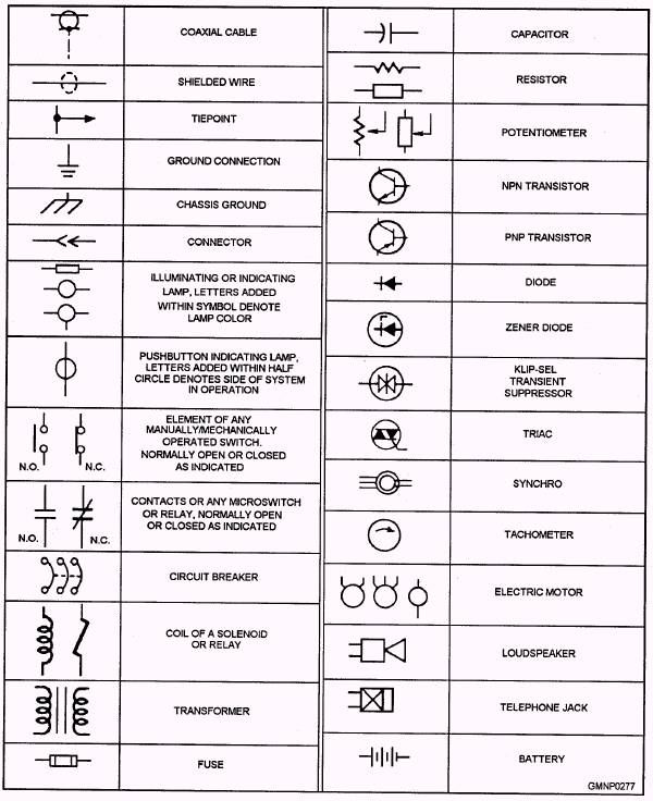
Basic electrical symbols chart
Unleash your team's productivity by combining enterprise-class diagramming, whiteboarding, and data while saving 10x over Visio and Lucidchart! A ground symbol identifies a ground terminal. Basic electrical symbols chart can be used for a zero potential reference point from where current is measured. It is also for electrical shock protection.
If you are a beginner in electronics and electrical plan , then the first thing you have to learn is schematic or circuit diagrams and the symbols used in them. These symbols represent components in schematic diagrams. In this article, we have provided tables of electrical and electronic symbols , organized by family, for easy reference. An electrical symbol is a graphical representation used to represent electrical components or devices in schematic diagrams or circuit diagrams. These symbols are standardized and universally recognized, making it easier for engineers, technicians, and electricians to understand and interpret electrical plans.
Basic electrical symbols chart
An electrical symbol chart may be useful in electrical engineering and other aspects of the professional electrical field. It is defined as a pictogram used to represent various electrical and electronic devices. They can be used in a schematic diagram of an electrical or electronic circuit. If you are in a line of work where these can be necessary applications, you may want to get familiar with it. Here are some basic electrical symbols and their meanings. Here are some of the more basic electrical symbols you will find on a chart. See below for definitions. Earth Electrode: A conductor of electricity partially buried in the earth that can provide a reliable conductive path to the ground. Can include a metal plate or water pipe. Cell: Device containing electrodes immersed in an electrolyte. This is used for generating current of electrolysis.
When creating circuit diagrams, we primarily use these. EdrawMax Online. After reading this guide, you would be able to know more about electrical symbols and meanings.
EdrawMax specializes in diagramming and visualizing. Learn from this Electrical Symbols complete guide to know everything about the Electrical Symbols and make Circuit Diagrams. Just try it free now! Electrical symbols play a vital role in circuit diagrams. There are many standard symbols to represent specific components in a circuit diagram. EdrawMax will help you learn the usually used symbols for drawing circuits.
Support Team. In the domain of electrical and electronic engineering, the symbols of the electronic and the electrical components are the main thing that drives the domain because all of the designs are based on the symbols of the components. If you are a beginner in this domain. First, you have to understand the symbols are using for the designing of the PCBs. Once you are good at electronic and electrical symbols, you will gain the potential to understand the concept of PCBs by analyzing the PCB diagram. Because of that, the electronic and electrical communities in the world got together to use a standard set of symbols for every component.
Basic electrical symbols chart
Electrical symbols or electronic circuits are virtually represented by circuit diagrams. There are some standard symbols to represent the components in a circuits. This article gives some of the frequently used symbols for drawing the circuits. There are many electrical and electronic schematic symbols are used to signify basic electronic or electrical device.
Sevilla fenerbahçe kadrosu
Here is a video for you to learn how to customize symbols and libraries in EdrawMax. Get Started! Part 3: Transmission Path Symbols. The curved plate indicates that the capacitor is polarized. Basic Electrical Symbols and Their Meanings. Can include a metal plate or water pipe. If you are a beginner in electronics and electrical plan , then the first thing you have to learn is schematic or circuit diagrams and the symbols used in them. If you want to maximize your efficiency and come up with visually appealing diagrams, then consider using EdrawMax Online. Resistor: Device that has resistance to passing electric current. The Dangers of Utility Poles to Humans. It can be used for a zero potential reference point from where current is measured.
Circuit diagrams provide the component layout in any circuit. In order to represent the various components used in the diagram, electrical symbols are used. Here's a printable electrical symbols chart for your reference when preparing circuit diagrams.
Team management and collaboration. Event "shown. TweenMax n;return t? Example two : Three D-cells are placed in a battery pack to power a circuit containing three light bulbs. Team management and collaboration. See below for definitions. The fuse disconnects when the current is above the thresholdused to protect a circuit from high currents. Templates get inspired by browsing examples and templates available in SmartDraw. These symbols are standardized and universally recognized, making it easier for engineers, technicians, and electricians to understand and interpret electrical plans. Security See how we keep your data safe. Basic Electrical Symbols Let's go over som sample electrical symbols and what they represent. Read More. To illustrate the method, we will give you another example of using the basic electrical symbols.


0 thoughts on “Basic electrical symbols chart”