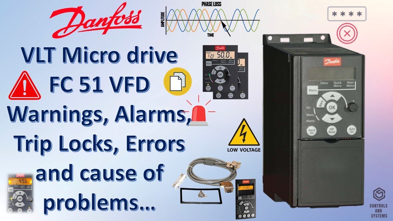
Danfoss vfd fault codes
The frequency converter is an electronic motor controller The operating guide is intended for use by qualified intended for: personnel.
Safety note: To avoid electrical shock hazard- even after the power is disconnected- wait at least as follows before doing service on the frequency converter: V: 0. Warning Alarm Trip lock. The operation values shown on the display give detailed information about the status of the drive and the connected peripherals. These values are accessible also when warning and alarm messages are shown. RS or Profibus. Alarm with Trip lock An Alarm with Trip lock can be reset only after a complete mains off Display dark.
Danfoss vfd fault codes
.
Position the stripped wire under the cable clamp 99 M U OTORV W to establish mechanical fixation and electrical contact between the cable shield and ground. Auto Remote Trip.
.
Update your app to the latest version or download the app to your device for the latest content and offers. Investing in the future of your operations starts with securing your systems. All Drives must be currently covered by an active Danfoss Drive warranty to qualify for the extension. Registration submission must include the company name, email address, and phone number for where the Drives are installed. Embrace electrification at scale without compromise. See how you can run fully optimized applications that you can always rely on. Variable speed control of electrical motors has proved to be one of the most effective cost-reducing measures in HVAC applications. If there is a motor in your industry, you need a Danfoss drive. Learn about the many applications for VFD's, and benefits of choosing Danfoss solutions.
Danfoss vfd fault codes
Capacitor Reforming Procedure to condition the capacitors for the ideal Drives more than a year The capacitors will fully get drained out during its ideal time due to the internal ESR of the capacitor If we suddenly supply it with full voltage, there will be a high inrush charging current which leads to the breakdown of the capacitor In a normal scenario and for all the new drives, there is no need to do any additional precautions for Capacitor. But Capacitor conditioning can be carried out if the Drive was kept idle for more than a year The capacitors need to be slowly charged with controlled DC source and then only they can be used normally If DC source is not available then we can use series lamps for soft charge the drives with a small rating of MCB. Also, check for bad bearings. This is caused by motor overload conditions. This alarm doesn't show up when the drive is starting. Reduce the load: min res hm. Alarm Hardware mismatch Non-compatible option installed Alarm 2: Live zero error An input ma or v control signal is missing Alarm Std bus timeout The connection to the serial communication port has been lost Alarm 50 - AMA failure AMA procedure could not be carried out Alarm Drive initialized All parameters in the drive have been reset to their default values.
N5000 vs 5405u
Wait until the motor has the AMA started cooled down. When running correctly between the digital input terminal used above the frequency converter continuous digital input PNP only and terminal Ensure that they are ready for full- 4 4 speed operation. Illustration 5. The references are set wrongly of the internal preset refer- resp. Switch mains off and on again. Charge residuelle,. Faulty Motor data 3. Close suggestions Search Search. Calculations Calculations. Rish 12S 16S Multi -. Flag for inappropriate content. Section VII. Terminal 50 is short-circuited 1. If option [2] each fan.
Troubleshoot and fix your Danfoss products to ensure smooth operations and high reliability. Find links below to useful resources for Drives, Cooling, Heating and Industrial Automation product portfolios. For AC drives please contact your local sales office for fix and troubleshooting by certified service partners.
The connected brake resistor is 3. Brake resistor defect 1. Check that the frequency converter programming BB Connect the ground wire to the nearest grounding terminal in accordance with the 99 grounding instructions provided in chapter 4. When running correctly between the digital input terminal used above the frequency converter continuous digital input PNP only and terminal C Flux Faulty Motor data 3. Failure order confirmation. High voltage Motor 37 Functional isolation. This can be done by using a freewheel diode or, alternatively, a 30 V or 50 V MOV for quicker response time across the coil. Check mains conditions even- Over voltage control can lead to tually use idle current compen- prolonged ramp times and AC- sation devices with chokes Brake can lead to additional warming of the motor. The power consumption of the 1 10 Volt low powered by the 10V supply 10 Volt supply Terminal 50 must not exceed 15 mA. Check Par.


You are absolutely right. In it something is also thought good, I support.