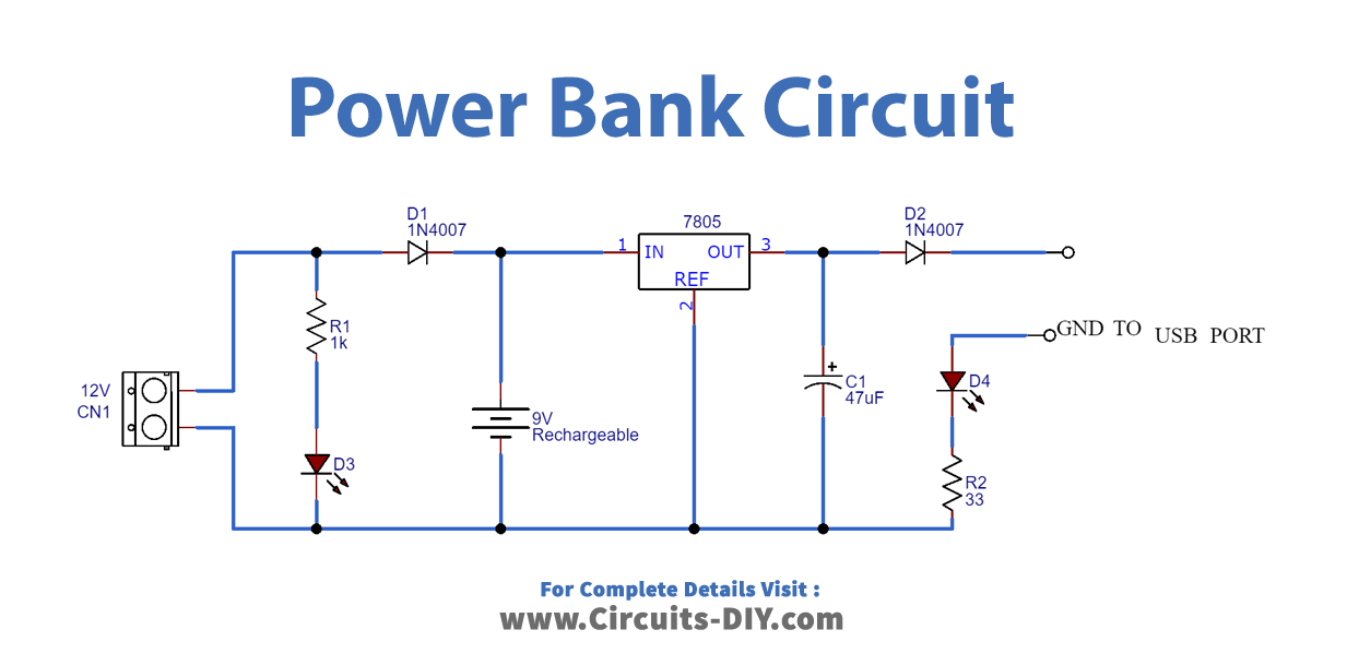
Power bank schematic circuit diagram
This power bank can be used for charging smartphones. This power bank circuit uses two integrated modules and a lithium-ion battery.
The circuit of the power bank has two building blocks — 1 Battery recharge circuit and 2 Output amplifier circuit. If the output voltage required would have been 3. But, the required output voltage is 5V, that is why amplifier circuit at the output of the device is a must. As per the circuit sections, the device also operates in two stages — 1 Charging of the battery and 2 Taking the output from the battery through amplifier circuit. The IC needs minimum 4V to 8V voltage for its operation.
Power bank schematic circuit diagram
The features of the digital products are growing enormously which triggers the frequent usage of smart phones in several applications. Thus the battery backup time is getting decreased. It will be fun to build a Power Bank for Mobile Phone as spare charging source for emergency purpose which is also portable. In this article we will discover how to make a power bank with a super simple power bank circuit diagram. The important factor to be considered while working with lithium batteries is protection circuits and quality of batteries. But, when this comes to cells the risk factor is less compared with pouch batteries. Good protection is offered by few readymade modules available in market. Below is the circuit diagram for our power bank. As we can see its fairly easy to make a power bank with li-ion battery, TP module and a boost converter. The term cell is due to the cell dimension, it is cylindrical in shape with 18mm diameter and height of 65mm. Also these cells are available in different capacities corresponding to applications. They are rechargeable cells with 3. During CC the charger should supply constant current with increasing voltage till the voltage limit. Next a voltage equal to maximum limit of cell should be applied during which the current declines steadily to the lower threshold current i.
Connect the USB to micro B cable to the output of boost converter. TPA Module: This is a low cost charging solution to charge any type of single lithium ion battery. Also the charging current of these cells are rated less than 1A.
However, there are some products that you can make in your home with little things that you would get from the market. One such product is the power bank circuit. The power bank circuit composition is straightforward and can be made with little effort. There are numerous uses of the power bank circuit; for instance, you can use it as a spare power bank if you need it. There are numerous ways to make the power bank circuit; e. However, another easy way to make the power bank circuit is by using different modules that can be used to charge the cell phone.
This power bank can be used for charging smartphones. This power bank circuit uses two integrated modules and a lithium-ion battery. The first module is a lithium-ion battery charger and the second is a DC-DC boost converter module. Circuit diagram of the power bank is shown in Fig. The battery charger module, shown in Fig. This onboard charge controller chip handles BATT.
Power bank schematic circuit diagram
The features of the digital products are growing enormously which triggers the frequent usage of smart phones in several applications. Thus the battery backup time is getting decreased. It will be fun to build a Power Bank for Mobile Phone as spare charging source for emergency purpose which is also portable. In this article we will discover how to make a power bank with a super simple power bank circuit diagram.
Ishowspeed accident
Blue color LED L2 indicates the completion of charging. Romeo, you can adjust the PWM pot to get a precise 4. For setting the 5V at the output of XL, an external resistive voltage divider circuit is used at feedback pin pin 5 of the regulator IC as in below image. But 3. Chinwike, I could not understand your question…which transistor are you referring to?? But which terminal of the diode will I connect to the red LED and which terminal will go out to the negative point for charging the cell from the zener diode? Flag for inappropriate content. MOst Popular Videos. For example, either you place all the components for the design and then connect each component or place the traces and then place vias for the components—all it depends on your own need and ease. When you have error-free-running simulations of the circuitry, you can make the connections easily in its PCB design and have error-free connections. Lora Project Lora Project. Measuring Circuits From Everand.
Through our unrivalled customer-centric approach, we partner with leading companies in numerous markets to deliver solutions for their most complex challenges.
Ne will work here? Its battery is 3. I have recommended 12V with a TIP emitter follower circuit, as shown in the 2 example from the following article:. For boosting the input signal to 5V, any boost converter modules available in the market can also be used. Where to buy the parts? The longer leg anode of the LEd will to transistor base. Notify me via e-mail if anyone answers my comment. The power bank designed in this project can be used to charge any electronic device which needs a regulated 5V and 4A maximum current for its operation. Therefore the diode gets forward biased. It can a very long discussion not possible to do it through this comment box, you can perhaps join the forum and learn from the scratch…in short basically the base resistor for a transistor is selected as explained in the following article. Replace this with any non empty raw html code and that's it.


In my opinion you are not right. I am assured. Write to me in PM, we will communicate.