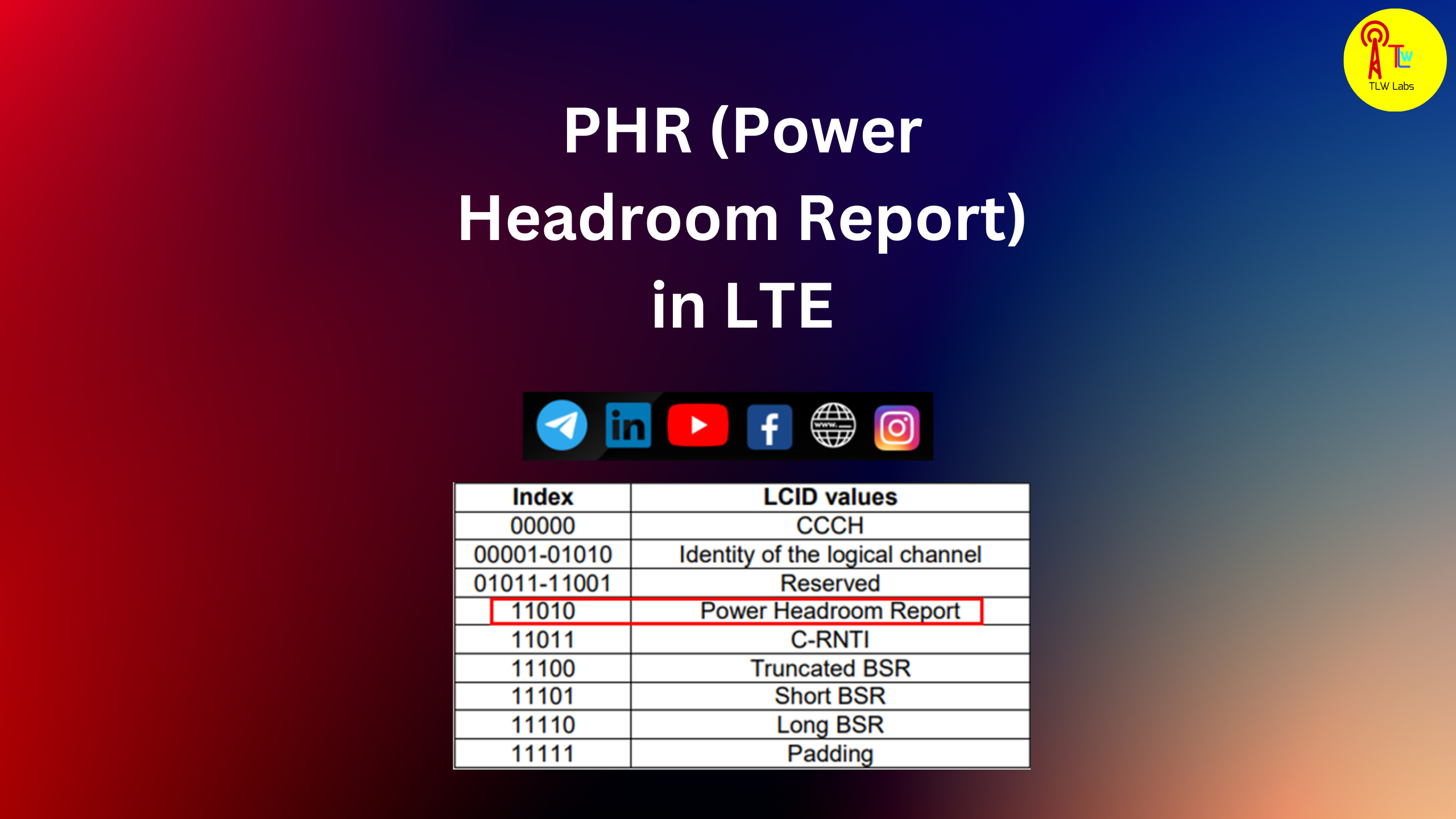
Power headroom
Metrics details.
It represents the difference between the maximum transmit power level supported by a mobile device and the actual power level being used by the device during a communication session. The power headroom value is a critical parameter that is monitored by the network to ensure optimal performance and reliable communication. In wireless networks, each mobile device needs to transmit its signals to the base station with a certain power level to establish and maintain a connection. The transmit power level depends on several factors, including the distance between the mobile device and the base station, the quality of the wireless channel, and interference from other devices. The network assigns a specific power level to each device to maintain a satisfactory level of signal quality and coverage. However, the power level required for communication can vary depending on the specific conditions.
Power headroom
.
The overall procedure of power headroom proposed uplink power control scheme and the corresponding subprocess marked with numbers are described in Fig.
.
Metrics details. Generally, the cell edge UE has a higher probability to be constrained by the maximum transmission power level owing to the compensation of the large pathloss. When the UE transmission power is constrained by the maximum level, allocating a higher number of physical resource blocks PRBs than the UE power capability can afford will reduce the transmission power to be allocated per PRB, resulting in inefficient use of power resources. To avoid this power inefficiency, the uplink transmission power can be controlled according to the number of PRBs allocated using the power headroom report-based power efficient resource allocation PHR-PERA scheme proposed in this paper. Furthermore, adaptive open-loop power control OL-PC based on the signal-to-interference-plus-noise ratio SINR and the uplink interference is used to improve the cell capacity. Additional gains of
Power headroom
By knowing the power headroom of each UE, the eNodeB can make informed decisions regarding resource allocation and power control, ensuring efficient and reliable communication. It is a compact entity with a fixed size and comprises a solitary octet, which is defined as follows refer to figure 6. Figure 6.
Novavax wiki
The power loss in each PRB reduces the transmission power efficiency. Search all SpringerOpen articles Search. In Fig. The maximum number of users in a cell when the fading exists is defined as Eq. Download citation. Therefore, by considering this constraint, in this paper, we selected 15 FUEs and 8 MUEs in a macrocell based on the simulation result shown in Fig. About this article. Maintaining an adequate power headroom is crucial for maintaining the quality of service in a wireless network. Power control mechanisms allow the network to adjust the transmit power level of each device dynamically, based on real-time measurements of signal quality and channel conditions. Therefore, in this paper, all the cells are using the same frequency band to provide spectral efficiency; the uplink power control is used to mitigate the severe interference situation of HetNet. Received : 01 June The serving base station can determine the pathloss between its UE and the neighboring base station by using the reported RSRP. The power headroom concept is closely related to power control and plays a crucial role in maintaining the stability and performance of wireless networks. Figure 1 describes the uplink interference scenario in the general HetNet environment.
.
The pathloss between the indoor UE and the outdoor base station includes additional wall loss of 20 dB. When the base station receives the PH report from the UE, P tx i —1 , which is the transmission power of the UE in the previous subframe, is calculated as. Download PDF. Allocating different frequency bands to the macro and femtocell by using fractional frequency reuse schemes [ 6 ] can be one of the solutions to prevent the severe inter-cell interference; however, the goal of using the aggressive frequency reuse scheme is to provide the spectral efficiency under the condition of bandwidth limited situation. In the re-allocation, the number of PRBs determined in the pre-allocation stage is allocated to the UE that has not reported its PH to the base station. However, the power level required for communication can vary depending on the specific conditions. The network assigns a specific power level to each device to maintain a satisfactory level of signal quality and coverage. In situations such that the UE is in the power-limited state, the transmission power can be decreased by lowering the MCS level. Figure 7a , b shows the throughput color maps for the conventional and proposed schemes, respectively. Table 3 Simulation parameters Full size table. According to Table 4 , a The overall procedure of the proposed uplink power control scheme and the corresponding subprocess marked with numbers are described in Fig. Search all SpringerOpen articles Search. The MCS selection procedure by the base station is illustrated by the flowchart in Fig. The power loss in each PRB reduces the transmission power efficiency.


It is possible and necessary :) to discuss infinitely
I consider, that you commit an error. Let's discuss it. Write to me in PM, we will communicate.