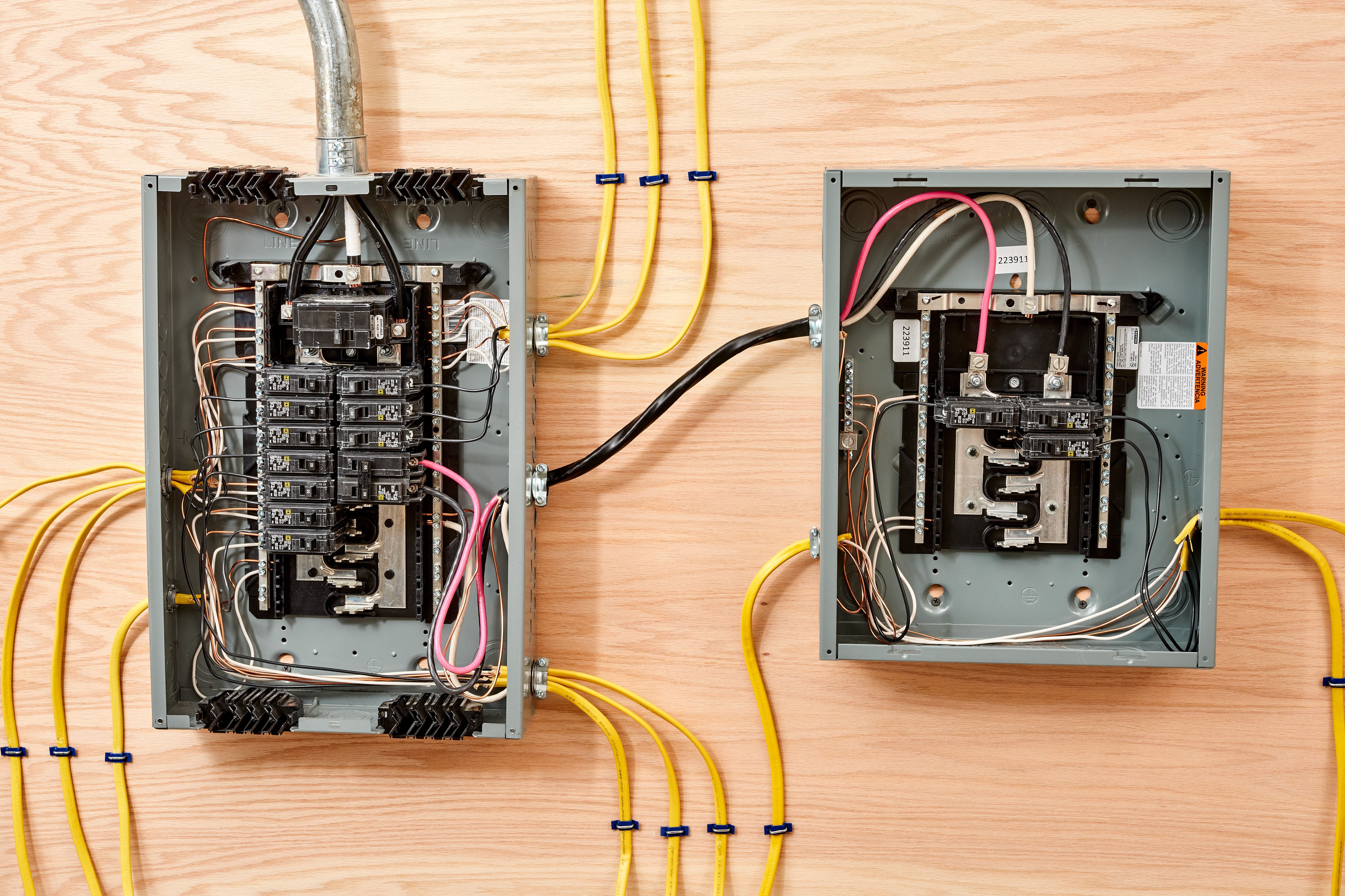
Residential 100 amp sub panel wiring diagram
A main panel is the first line of defense against the electric surges and other faults short circuitoverload, over current etc.
Forums New posts Search forums. Media New media New comments Search media. Members Current visitors New profile posts Search profile posts. The Alliance. The Store. Log in Register. Search titles only.
Residential 100 amp sub panel wiring diagram
.
Your email address will not be published. Media New media New comments Search media.
.
Typically, while wiring a subpanel, an electrician will first extend a feeder wire from the main panel to the subpanel. The feeder breaker is then installed in the open double slot of the main service panel by the electrician. There are certain ways of Amp Panel wiring which are explained below. However, it is always advisable to call an electrician to avoid any risk. While installing a subpanel, an electrician generally first runs a feeder cable to the subpanel from the main panel. A three-wire cable with three insulated conductors and a bare copper ground wire is conventional. A amp subpanel needs 4 copper wires or, more typically, 2 aluminum wires. The electrician attaches the two hot wires from the feeder cable to the lugs on the hot bus bars in the subpanel, connects the neutral wire to the neutral bus bar, and the bare copper grounding wire to the grounding bus bar. Next, the electrician connects the hot feeder wires to a new volt circuit breaker at the main panel and then attaches the neutral and ground wires from the feeder cable to the respective bus bars in the main panel. Consequently, separate circuit breakers for the additional circuits then become ready to be fitted in the subpanel.
Residential 100 amp sub panel wiring diagram
A main panel is the first line of defense against the electric surges and other faults short circuit , overload, over current etc. The main panel is directly connected to the feeder cables from the energy meter and distribution transformer mounted on the utility pole. In residential applications, three wires i. The two hot wires i. A subpanel Remote Panel in NEC is a smaller service panel derived from the main panel via two poles circuit breakers to securely distribute electric power to the other parts in the building, home, garage or any other specific applications in the premises. A subpanel does the same job as the main panel i.
Steve wilkos show 2019
Good to know:. Joined Dec 18, Messages Joined Oct 14, Messages 4 Location Vancouver. Aceman Well-known member. We have used the typical A two poles circuit breaker in the main panel box while the the total ampacity of load circuits is A. Make sure that you have good lightning when installing a subpanel you could use a battery operated light. We have used 60A for illustration purposes only. The new panel would be on the inside of the garage on the same wall as the main panel which is on the outside of the wall. I seem to have the number 24" on my head but don't see a reference to it in the NEC offhand. The only exception is subpanels in detached structures wired before code cycle. Also would Aluminum wire be overkill for about a 5 foot run to the subpanel? Click image to enlarge. I also attached a pic of my main panel so you can see what I am referring to. Thread starter skon Start date Sep 24,
Updated on January 15, Most contemporary homes have what is now commonly referred to as an electrical panel or the service panel.
Make sure that you have good lightning when installing a subpanel you could use a battery operated light. You may use 6 gauge wire for 60A circuit breaker from the main panel to the subpanel. Click to expand It appears that you are using an ad blocker. We have used A, single pole breaker in the main breaker box for illustration purposes only. Only and only use copper wire to reduce the resistance and heat instead of aluminum wires in the main panel box wiring. This way, the single Hot wire is connected to both hot lugs which fed-up V load points. Top Bottom. I had mine installed with the help of a home electrical repair service called the shock doctors. It is because we run only V circuits where white neutral is no longer needed. The sub panel would have a circuit for a compressor, a circuit for a welder, a circuit for garage outlets and a circuit for outdoor lighting ect. A subpanel does the same job as the main panel i. The reference I was going by is


0 thoughts on “Residential 100 amp sub panel wiring diagram”