Usfd manual
Ultrasonic testing of rails was introduced over Indian Railways during early 60s. From a humble beginning, this technique has graduated itself to an extent that today it is one of the most powerful tools of preventive maintenance of usfd manual permanent way, usfd manual.
Disclaimer: This Compilation is for educational reference only. For details refer original correction slips. Ultrasonic testing of rails was introduced over Indian Railways during early 60s. From a humble beginning, this technique has graduated itself to an extent that today it is one of the most powerful tools of preventive maintenance of the permanent way. During the last 40 years of its existence, a large number of testing procedures, specifications, guidelines and criteria have been issued from time to time based on the experience gained. The advent of fracture mechanics concept coupled with state of the art steel making technology has thrown open a new dimension in the periodicity of ultrasonic examination.
Usfd manual
.
Crushing usfd manual 1. Invariably the flaw will be on that side of the rail head, which is nearer to the weld.
.
Ultrasonic testing of rails was introduced over Indian Railways during early 60s. From a humble beginning, this technique has graduated itself to an extent that today it is one of the most powerful tools of preventive maintenance of the permanent way. During the last 40 years of its existence, a large number of testing procedures, specifications, guidelines and criteria have been issued from time to time based on the experience gained. The advent of fracture mechanics concept coupled with state of the art steel making technology has thrown open a new dimension in the periodicity of ultrasonic examination. The rate of crack propagation and fracture toughness characteristics of rails can be experimentally found which determine the critical crack size. Based on the above knowledge and experience, it was considered necessary to assimilate the entire information on ultrasonic examination of rails and present in the form of a manual so as to guide the ultrasonic personnel in testing, interpretation and decision-making. Subsequently, a revision was issued in in view of the experience gained in the field of USFD testing and maintenance practices. This revised edition is therefore prepared incorporating all the amendments and revisions. The provisions made are mandatory for all ultrasonic personnel and supersede all previous instructions in case they happen to be contradictory to the instructions contained in this manual. This revised version of the manual incorporates Correction Slip No.
Usfd manual
Disclaimer: This Compilation is for educational reference only. For details refer original correction slips. Ultrasonic testing of rails was introduced over Indian Railways during early 60s.
Ask fm bikini
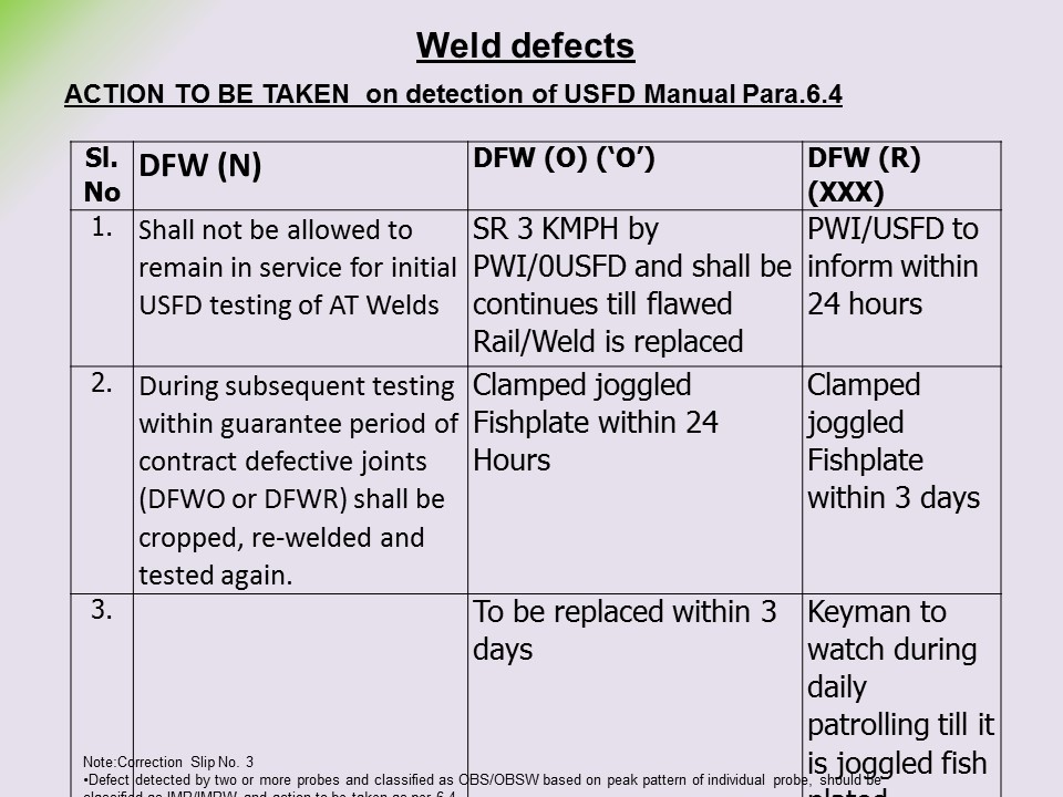
Reference is also to be made to Rly. The equipment shall be able to detect 12 mm dia. Wheel burns 9. The procurement of spares for a machine shall be done from Original Equipment Manufacturer OEMs of that machine only, in order to ensure compatibility of spares with the machine and to achieve consistent and assured quality of testing. Each weld failure shall be analysed by sectional Sr. Place the probe at approximately mm from the 5 mm dia hole on the web as shown in Fig. This examination shall be carried out for all rails by the manufacturer to the satisfaction of the inspecting agency. The probe shall be moved on the weld centre to scan the weld area. Whether within service life 6. The DFWR weld shall be replaced within three months of detection. Item Number 1. Typical oscillogram pattern for various probe positions are given for guidance as indicated below: i Probing from the rail table: Oscillogram pattern for sound rail will be as given at Fig. Base line and flaw peaks v Working of the junction box. Uploaded by Radha Krishnan.
.
In view of the design of the SEJs, testing is to be accomplished by hand probing. In order to find out the origin of detection i. The single rail tester has been utilised on Indian Railways for over 40 years and the double rail tester is of a relatively recent origin developed Ten years back. Diagonal at hole joint 4. The following characteristics shall be checked i Linearity of time base of flaw detector ii Linearity of Amplification of flaw detector iii Penetrative power iv Resolving power v Probe Index vi Beam angle. This adjustment should also be done with the help of respective potentiometer. They are generally inclined at the angle of 18oo and originate at a depth of mm below the running surface. The frequency of testing in this case is as per Para 6. At the same time, frequent watch over increasing incidence of defects is necessary. Move the probe in slight zigzag manner up to curve portion. Depending upon availability and feasibility of the testing, water, oil or grease can be used as couplant. The distance between probe index marks in the rig shall be adjustable and kept as mm and mm for 52Kg and 60Kg rails respectively while testing.


I confirm. I join told all above. Let's discuss this question. Here or in PM.