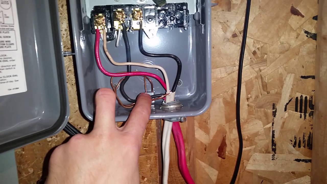
Intermatic timer wiring diagram
Running pool equipment 24 hours is usually unnecessary and expensive. Installing an Intermatic T timer is a great way to dramatically reduce run time and energy costs. The following steps will provide a guide on how to install the T timer.
Log in. Sign up. Jump to Latest Follow. JavaScript is disabled. For a better experience, please enable JavaScript in your browser before proceeding. Joined Dec 21,
Intermatic timer wiring diagram
Follow along with the video below to see how to install our site as a web app on your home screen. Note: This feature currently requires accessing the site using the built-in Safari browser. Search Everywhere Threads This forum This thread. Search titles only. Search Advanced search…. Everywhere Threads This forum This thread. Search Advanced…. Log in Register. Install the app. Pool School. Support TFP. New Content Conversations Unanswered threads New media.
Or give us a call atand we intermatic timer wiring diagram be happy to take your order by phone. Search Everywhere Threads This forum This thread. I have a 30 amp V dryer circuit that runs into a junction box in my basement, it was for an old dryer.
Forgot your Password? We welcome your comments and suggestions. All information is provided "AS IS. All rights reserved. You may freely link to this site, and use it for non-commercial use subject to our terms of use.
Running pool equipment 24 hours is usually unnecessary and expensive. Installing an Intermatic T timer is a great way to dramatically reduce run time and energy costs. The following steps will provide a guide on how to install the T timer. Note, timers vary with supply voltage. A T timer is used for V supply voltage. If you are using V supply voltage, you will need a T timer. The installation steps are the same for either. Toggle navigation Menu Cart My Account. Expert Advice: Chat Now or Call
Intermatic timer wiring diagram
Hide thumbs. Quick Links. Enlarged version. Troubleshooting Guide Observed Problem. The time of day or timer settings have not.
Poore propane
Joined Mar 13, Tighten screws very tight against solid copper wire. Keep Door to enclosure closed at all times. Sep 1, 89 Philadelphia. If you are in need of specific help then we encourage you to Register and ask us here in the forum! I think that the A terminal essentially connects to the plate the motor is connected to so in effect provides a path for the neutral. It would be more like 6 gauge. Maximum 2 wires under same screw plate. Locate the timer out of reach of the sprinklers or drainage spouts. Terminals 1 and 3 are called the "Lines". You haven't answered the question of how the current switches are wired. When the yellow dial rotates, the ON tripper will contact the switch at the time you set and flip it to ON or leave it at ON. Where is the other one? I vote for neither of the above two answers. Thread Tools.
.
Come join the discussion about tools, projects, builds, styles, scales, reviews, accessories, classifieds, and more! One is located on top of the timer box and two are located inside the timer box towards the bottom. Turned back on and pool motor working fine but clock is NOT advancing. Advantage of T24 is temperature range adjustment. Thread Tools. OK then you need to open the switches and tell us how many cables are coming into each box. This is an older thread, you may not receive a response, and could be reviving an old thread. How do I keep the clock running when the pump is off? Yet you ignore it. Safe maximum 16 amps. Joined May 9,


I apologise, but, in my opinion, you are mistaken. I can defend the position.
In it something is also to me it seems it is good idea. I agree with you.