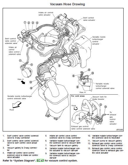
Zd30 engine diagram
C Price Based on manual transmission. Nissan Australia September The information in this Training Manual should not be interpreted as a basis for. Patrol Name Leadership.
Informacao e dados mecanicos Read less. Download Now Download to read offline. Recommended Fuel d Fuel d13 Eduardo Herrera. Common rail system for nissan. Common rail system for nissan Darcats. Cummins cm electronic control system service repair manual.
Zd30 engine diagram
Open navigation menu. Close suggestions Search Search. User Settings. Skip carousel. Carousel Previous. Carousel Next. What is Scribd? Academic Documents. Professional Documents. Culture Documents. Personal Growth Documents.
Search inside document.
.
Follow along with the video below to see how to install our site as a web app on your home screen. Forums New posts Search forums. Media New media New comments Search media. Members Current visitors. Log in Register. Search titles only. Search Advanced search…. New posts.
Zd30 engine diagram
Electrical wiring diagrams for the ZD30 engine are an essential component of any car enthusiast's toolkit. Whether you're building a custom car or simply replacing an old engine, having a wiring diagram on hand is invaluable. The ZD30 engine was first produced by Nissan in the late s and is still in production today. It is one of the most common engines used in cars, trucks, and other vehicles, and its wiring diagrams can be challenging to understand. This article will help you understand the basics of ZD30 wiring diagrams, how to read them, and how to use them to repair and maintain your vehicle. Wiring diagrams are essential tools for any mechanic, and understanding how to read them correctly is a key part of successful maintenance and repairs. The ZD30 engine was released by Nissan in the late s and is equipped with a variety of electronics and components. Wiring diagrams can help you identify and trace electrical connections, allowing you to diagnose and fix problems quickly and effectively. They can also aid in the installation of new components and upgrades to your vehicle.
Homemovies tube.com
Volvo wiring diagram fh Sergio Andres Aburto. Is it serviceable? Percentage Chart Percentage Chart. Dot Matrix Printers. Shacman Shacman. The piston is located inside the magnetic core. Ep Nwa 1 Ep Nwa 1. It is a simple matter of operating the ignition key within set time periods. The drive gear is connected to the high-pressure pump drive shaft by a plate coupling. Recently uploaded Electric-vehicle manufaturing F. Electrical resistance of the thermistor decreases in response to the temperature rise. The ECM regulates electrical current to the valve to either open or close it. ECU judges that the accelerator pedal is hanging. Make sure the fusible links on the positive terminal are not corroded.
If there are any features of this vehicle that sets it apart from other vehicles in its class, then mention those unique attributes here.
Ensure there is a sufficient vacuum supply coming from the engine driven vacuum pump. Pilot Injection Pilot injection precedes the usual injection ie, main injection and is the injection of a very small quantity of fuel. To download free nissan Reference patrol zd30 reference document you need to register. If anything contained within this document gives any doubt, please contact Nissan via a Non Vehicle related TechLine enquiry to clarify the information within this document. Original Title bea3cd16a3b35dea7b1d Each selected item is highlighted. To download free user manual porsche turbo you need to register. The design differs from the previous ZD engine as the viscous coupling is now a separate part from the water pump. This code is entered into the ECM at the factory via a special scan tool. Did you find this document useful? The main Sub Mode screen will appear over the Data Monitor screen. Then select another shim of a different size which will correct the valve clearance issue. Carousel Next. The injector assembly can be divided into the following two functional units; i Control section The control section consists of a control chamber, a magnet, a valve spring, an armature plate, a valve ball, a valve body, a valve piston and 2 orifices.


I can recommend to visit to you a site, with a large quantity of articles on a theme interesting you.